
What Is the Best UL FM Post Indicator Valve (PIV)?
2026-11-02
Finding a post indicator valve that actually holds up under real field conditions isn’t just about checking UL and FM boxes. Many valves pass the lab but struggle with corrosion, vague position indicators, or stiff handles after a few seasons. So what separates a truly dependable PIV from one that only looks good on paper? At DRIFCO, we’ve spent years answering that question in the field—not just in brochures. This guide breaks down what the best UL FM post indicator valve really needs to deliver, and why the details matter more than you think.
Choosing a UL FM Post Indicator Valve That Holds Up Under Pressure
The pressure rating stamped on a post indicator valve means little if the system can spike beyond it during start-up or valve closure. Look beyond the nominal 175 psi or 200 psi figure and ask how the valve behaves under repeated surge conditions. A cast iron body with brass internals may survive a static test but wear quickly when flow reversal and water hammer hit the seat disc. Request test data for cyclic pressure loading, not just a one-time hydrostatic proof.
Materials and coatings deserve more scrutiny than the marketing language suggests. Ductile iron offers better tensile strength than traditional grey cast iron, and an interior fusion-bonded epoxy lining can reduce friction and corrosion in wet systems. External hardware should be stainless steel or at least zinc-nickel plated; plain steel handwheels and fasteners rust within a season in coastal or industrial environments. If the valve will sit partially buried or exposed to road salt, check that the indicator stem seal is rated for continuous submersion, not just occasional splash.
Field performance often comes down to how easily the valve can be operated after years of inactivity. A gear-driven operator with a low input torque keeps firefighters or maintenance crews from resorting to cheater bars. The target plate or indicator window should be readable from ground level at a glance, and the open/closed position should lock firmly without drift. Test a sample valve yourself: close it fully against rated pressure, wait 24 hours, and see if the stem position holds or if leakage past the seat allows the indicator to creep.
Key Differences Between UL and FM Approved PIVs Worth Noticing
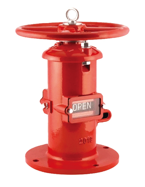
When you put a UL-listed post indicator valve next to an FM-approved unit, the catalog data may look nearly identical, but the underlying priorities split in meaningful ways. UL's evaluation tends to stop at the component itself: does the valve body hold rated pressure, does the operating mechanism survive repeated cycles, and will the indicator show open or shut accurately after exposure to weather. FM's process, by contrast, leans harder on how the valve performs as part of a larger risk reduction strategy. That often translates into stricter demands for tamper resistance, less wiggle room on leakage, and a preference for designs that make an incorrect position harder to overlook during a walkthrough.
Another worthwhile distinction shows up in field expectations. A UL listing alone may satisfy a local code official looking for a recognized safety mark. An FM approval frequently signals that the insurer or risk engineer wants details beyond the basic listing—like specific wrench sizes for the operating nut, corrosion resistance on buried stem components, or a supervisory switch that sends a distinct signal when the valve is moved from open. In warehouses or industrial sites, these extra FM-driven requirements can be the reason a contractor ends up swapping a code-compliant PIV for an approved model even though both look acceptable on paper.
Finally, think about maintenance and inspection. UL's standard gives you a solid baseline for a valve that can be opened and closed without breaking. FM-approved PIVs often come with documentation and testing cycles that assume someone will actually exercise the valve each year, so wear parts like the stem packing and target plate tend to be overbuilt for that routine. The practical takeaway is that the choice isn't just about a logo. It is about matching the valve's strengths to the scrutiny it will face after installation.
Installation Mistakes That Can Void Your PIV Certification
A certified PIV reader isn’t just a plastic box with a slot. The certification covers the exact model, its firmware version, the cable gauge, and how the unit is anchored. Swapping in a lookalike reader from a different batch because the original was backordered will quietly break the certification, even if every screw lines up. During a compliance review, that substitution is treated as a non-certified installation, and you’ll be told to rip it out and start over.
Field modifications are another trap. Technicians sometimes drill extra holes to route cables neatly or bend the mounting bracket to fit a narrow mullion. Those changes may seem harmless, but they can stress the internal components or alter the reader’s alignment with the credential. Certification tests were run on an unmodified unit in a specific orientation. Once you change that, the certification is void, and the facility is technically out of compliance until a certified installer verifies the repair.
Power and grounding mistakes fly under the radar because the reader often still works. Using a different power supply or tying the reader’s ground to a nearby metal door frame instead of the designated terminal can introduce noise or voltage drift. Over time, that leads to intermittent reads or premature failure, but from a certification standpoint, the damage is immediate. The installation no longer matches the approved documentation, which is all a certification body needs to pull the approval.
Why Material Choice Matters More Than You Think for PIV Longevity
Most people assume a PIV system fails because of the fan or the controller, but the truth is far simpler: the materials quietly degrade long before any mechanical part gives out. Cheap plastics become brittle after years of temperature swings, hairline cracks form around mounting points, and condensation finds its way into places it shouldn't. What looks like a minor cosmetic flaw is often the first domino in a slow, invisible breakdown.
Material choice also dictates how well the unit handles the constant, low-level stress of everyday operation. A housing made from UV-stabilised, impact-resistant polymer won't warp or discolour after a few summers in a warm loft. Stainless steel fixings resist the kind of corrosion that seizes up lesser units. These aren't luxury upgrades; they're the difference between a system that lasts fifteen years and one that quietly underperforms after five.
The real longevity test isn't the spec sheet — it's what happens when the warranty expires. High-grade materials keep air seals tight, prevent internal condensation from reaching electrical components, and maintain structural integrity even in poorly insulated spaces. Skimp on materials, and you're not just buying a cheaper unit; you're buying a future repair bill and a home that slowly loses its ventilation efficiency without anyone noticing.
A Practical Look at PIV Sizing and Flow Requirements
Sizing a pressure independent valve starts with the actual required flow rate and available differential pressure, not the line size. A PIV's real advantage is maintaining flow within a tight tolerance even when system pressure shifts, so you need to select one whose controllable range covers the required flow, not just the maximum. For example, a 2-inch valve might look fine based on pipe diameter, but if the design flow is only 1.2 GPM and the valve's minimum controllable flow is 2.5 GPM, you'll get hunting and poor temperature control. Check the manufacturer's minimum differential pressure across the valve at required flow; below that, the internal regulator cannot do its job.
Flow requirements should account for diversity and low-load conditions, not just peak design. Many PIVs are specified with too much safety factor, forcing them to operate near the bottom of their range. Instead, calculate actual coil flow at part load and verify the valve's turndown ratio. Also consider pressure drop: PIVs generally need a higher initial pressure drop than a standard two-way valve to maintain authority, but that extra drop buys you stability when other loops open and close. A common mistake is summing full-load pressure drops across parallel branches; use the critical circuit's pressure differential for sizing and let the PIV absorb the rest.
Maintenance Habits That Keep Your Post Indicator Valve Working Reliably
A monthly walk-around of the valve’s immediate area catches problems before they become failures. Clear away mulch, snow, or debris that blocks the valve body or target indicator. Wipe the sight glass or indicator window with a damp cloth so the open/shut position reads correctly from a distance. If the valve is in a pit, make sure the drain holes are not clogged and the cover lifts without binding.
Every quarter, open and close the valve through a full cycle—never just a partial turn—to keep the stem and internal gate from seizing. While you’re at it, apply a thin coat of marine-grade grease to the stem threads and the wrench nut, but avoid over-greasing, which attracts grit. After cycling, confirm the target indicator returns to the exact same position and the tamper switch sends a signal to the fire panel or monitoring station. If the switch feels loose or the indicator window is fogged, replace the gasket before moisture works its way inside.
Keep a small logbook or digital note with date, person, and any resistance felt during operation. This record helps you spot slow changes—like increasing torque or a target that’s harder to read—long before the valve stops working. If the valve sits outdoors, inspect the paint and touch up chips with cold-galvanizing spray to ward off rust. Tighten mounting bolts once a year, but don’t over-torque them; a snug fit that allows the valve to cycle without flexing is enough.
FAQ
A post indicator valve is a ground-level valve assembly used to control water flow to a building's fire sprinkler or standpipe system. It sits above ground on a vertical post, with a visible indicator showing whether the valve is open or shut. The 'post' part refers to the upright housing, while 'indicator' points to the flag or target that displays the valve position.
A PIV earns both marks by passing separate test protocols. UL verifies compliance with safety standards for mechanical endurance, pressure containment, and corrosion resistance. FM Global goes further by simulating real fire conditions and evaluating loss prevention performance. Having both means the valve has been vetted for reliability, leakage, and long-term durability, so it satisfies most insurance carriers and local codes.
Ductile iron is the top choice for buried and exposed valve bodies because it resists corrosion and handles high pressure better than cast iron. Some buyers opt for epoxy-coated ductile iron for extra protection in aggressive soil. Avoid plastic or lightweight alloys unless the project specs explicitly allow them; they may not hold up to accidental vehicle impact or freeze-thaw cycles.
Sizing depends on the main supply line. Most commercial systems use a 6-inch or 8-inch PIV, but smaller 4-inch models exist for residential or light hazard jobs. Check the valve's pressure rating and flow coefficient (Cv) against the hydraulic demand of your sprinkler system. Oversizing is generally safer than undersizing, but it costs more and may require a larger vault or thrust block.
Yes. The biggest ones are burying the valve too deep, which hides the indicator window, and failing to provide a concrete thrust block or restraint. Also, many installers forget to lubricate the stem before backfilling, leading to stiff operation later. Always keep the target window face accessible and at least 40 inches above grade, and make sure the valve is opened fully before the final inspection.
Yes, as long as the valve's flow capacity matches the combined demand. For combined systems, choose a PIV with a non-rising stem and a clear open/closed target so firefighters can quickly confirm status from a distance. Some models offer a tamper switch that sends a signal when the valve is moved from the open position, which is required by NFPA 72 for supervised systems.
Exercise the valve at least once a year by closing it fully and reopening it, then check that the indicator target returns to the exact open position. Clean any debris from the target window and lubricate the stem threads with a waterproof grease. Also, look for signs of corrosion or paint damage on the post, and verify the tamper switch wiring is intact if installed.
Look for a full-port design, a stainless steel or brass internal stem, a sealed indicator mechanism that won't fog or jam, and an epoxy-coated ductile iron body. The best units also include a factory-installed tamper switch and a weatherproof cap for the target window. Budget models often skip the corrosion-resistant coating and use thinner castings, which can warp under pressure or crack during freeze-thaw cycles.
Conclusion
Finding a post indicator valve that actually earns both UL and FM approval isn't just about picking a familiar brand. The real test comes down to how the unit behaves under sustained line pressure, especially in older systems where surges are common. A valve that looks identical on the outside may have internal differences in stem seals, flange ratings, and tamper-switch wiring that only become obvious after a few seasons. UL listing often centers on structural integrity and pressure endurance, while FM approval leans more toward loss prevention and real-world installation conditions—so matching the right certification to your risk profile matters more than relying on one standard alone.
Beyond approvals, material selection quietly dictates whether the PIV survives corrosive soil or coastal air. Ductile iron bodies with epoxy coating tend to outperform painted cast iron over a decade, but many failures trace back to hasty installation rather than the hardware itself. Setting the depth incorrectly, misaligning the target plate, or overtightening the stem can void certification without any visible leak. Then there's sizing: a PIV that’s too small starves the riser during a real discharge, while oversizing adds needless friction and cost. Once installed, a simple monthly inspection routine—exercising the wrench, checking the indicator window, and clearing debris from the handwheel—does more for reliability than any premium feature. The best UL FM PIV is rarely the most expensive one; it’s the one matched to actual flow demands, installed by someone who reads the torque specs, and checked often enough to catch wear before it becomes a code issue.
Contact Us
Contact Person: George
Email: [email protected]
Tel/WhatsApp: 13863633883
Website: https://www.es-fire.com