
PM Fiber Fusion Splicer Supplier Offering Precision Splicing Solutions for Optical Networks
2026-10-13
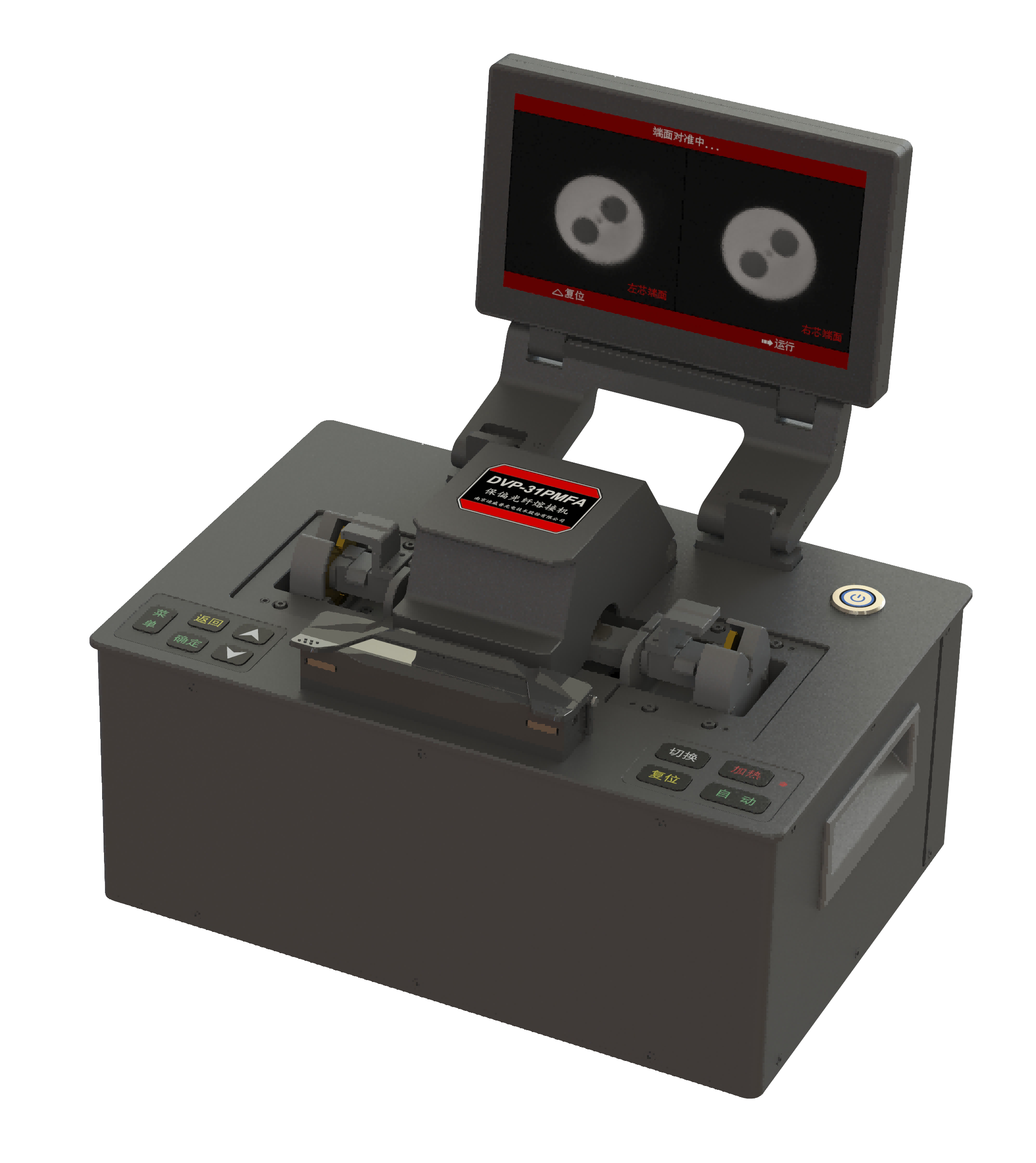
Precision PM fiber splicing is not just about aligning cores—it’s about preserving polarization state, minimizing loss, and keeping optical networks stable under real-world conditions. Yet many teams still struggle with inconsistent splices that erode network performance. DVP steps in as a PM fiber fusion splicer supplier with a clear focus: repeatable, high-accuracy splicing solutions designed for the demands of modern optical networks. In this post, we’ll explore what sets DVP’s approach apart and how it helps you achieve the precision your network depends on.
Polarization-Maintaining Fiber Needs More Than Standard Splicing
When splicing polarization-maintaining fiber, the usual core-alignment routine falls short because it treats the fiber as a symmetric waveguide. PM fiber carries stress rods or an elliptical cladding that defines a slow axis, and if the splicer ignores this asymmetry, even a perfect core match can leave the polarization axes rotated relative to each other. The result is cross-coupling, a drop in polarization extinction ratio, and unstable performance in interferometric sensors or coherent systems. Standard splice loss readings won't catch this because they don't measure polarization.
A proper PM splice starts with fiber identification and orientation. Panda, bow-tie, and elliptical-clad fibers each present different stress member geometries, so the splicer must be set to the correct profile. Many machines offer a PM mode that uses side-view imaging or direct polarization analysis to rotate one fiber until the stress elements align. This isn't a one-time setting—ambient temperature, electrode condition, and fiber geometry all shift the alignment point, so periodic recalibration and a short stabilization arc are often necessary to hold the axis through the joint.
Beyond the machine, the proof comes from measuring polarization extinction ratio after splicing, not just insertion loss. A splice can show 0.02 dB loss and still ruin a 30 dB PER link. Some installers use a polarized broadband source and a polarizer to check the axis continuity in real time, adjusting the rotation before the final splice. Others pre-tack the fibers, measure PER, and re-arc only if the ratio holds. This extra attention is what separates a PM splice that works on day one from one that degrades under thermal cycling or mechanical stress.
Checking a Supplier's Real Extinction Ratio and Angle Accuracy
To get a true picture of a supplier's extinction ratio, you can't just rely on the number printed in the datasheet. Set up a stable laser source, a high-quality linear polarizer as reference, and a calibrated optical power meter. Rotate the device under test through a full 360 degrees while recording the minimum and maximum transmitted power. The ratio of those two values is the real extinction ratio. Many suppliers test at a single wavelength or with a simplified setup, which can inflate the figure by several dB. Running the measurement at the edges of the specified wavelength band and at different temperatures will quickly expose any hidden weaknesses.
Angle accuracy is another common point of overstatement. Mount the polarizer or waveplate on a precision rotation stage with a resolution of at least 0.1 degrees. Find the extinction minimum by stepping through small angular increments around the expected axis. The deviation between the mechanical marking or keyway and the actual minimum gives you the true angular error. Keep in mind that mounting stress or non-parallel optical surfaces can shift the axis by a fraction of a degree, so repeat the measurement several times after demounting and remounting the component. A spread in repeated measurements often reveals more about quality than a single pass would.
Finally, compare your measured values against the supplier's tolerance claims under the same environmental conditions. A supplier that lists extinction ratio at 25°C but doesn't mention performance at -5°C or 70°C may be hiding a significant drop. If possible, request a full test report with raw data, not just summary statistics. The strongest verification is cross-checking three units from different production batches; consistent results across all samples tell you the process is under control, while large unit-to-unit variation points to weak manufacturing discipline rather than an honest specification.
Field Factors That Quietly Lower PM Splice Performance
Splice closures often look robust from the outside, but subtle environmental and installation factors can degrade performance long before any visible failure. High humidity trapped inside the enclosure, for example, accelerates corrosion on connector end faces, while temperature swings cause micro-expansion that loosens fiber alignment. Even a small amount of dust settling during a rushed field assembly can introduce insertion loss that compounds over time.
Another quiet culprit is cable strain transferred through the splice tray. When drop cables are not properly secured with strain-relief brackets, daily wind load or pedestrian vibration slowly pulls on the splice sleeve. This micro-movement is rarely detected during initial OTDR testing but shows up months later as intermittent faults. Technicians often blame the splice itself, overlooking how a tight bend radius near the closure entry can cause macrobend loss that mimics a bad fusion.
Finally, the choice of sealing materials plays a bigger role than expected. Gel seals that work perfectly in temperate climates may stiffen in cold weather, allowing moisture ingress around the cable ports. Likewise, using a generic mechanical splice instead of a fusion splice in a high-humidity duct can lead to gradual reflectivity drift. These field factors don't trigger alarms immediately—they quietly erode the margin that separates a passing link from a failing one.
Where Precision PM Splicing Shows Up in Live Optical Networks
Precision PM splicing matters most in segments where polarization state directly affects signal integrity. In coherent transmission links, especially those using dual-polarization modulation, the launch and receiver tails often rely on PM fiber to keep the orientation aligned. A poor splice here doesn't just add loss; it introduces polarization crosstalk that shows up as a higher bit error rate on one polarization axis long before the optical power budget takes a hit.
Field technicians encounter it again in fiber-based sensing arrays, where PM fiber is used to maintain interference visibility over long distances. Splices between the sensing cable and the interrogator must preserve the slow-axis alignment within a couple of degrees, otherwise the returned signal fades. The same discipline applies to RF-over-fiber links feeding remote antenna units, where a misaligned splice can change the phase delay enough to cause noticeable distortion in the recovered analog waveform.
Less obvious but equally demanding are test and monitoring ports inside live network nodes. When optical time-domain reflectometry or distributed acoustic sensing is overlaid on an active route, the reference path often includes PM fiber. A splice that drifts over temperature or vibration can make the baseline trace unstable, leading maintenance crews to chase ghosts that aren't actually in the span.
Practical Questions Before Choosing a PM Fusion Splicer Partner
When you start comparing potential partners for PM fusion splicing, the first thing to dig into isn't the spec sheet—it's their actual repair and calibration workflow. A lot of vendors will tell you their machines hold extinction ratios above 30 dB in the lab, but what happens after six months of field use, dust exposure, and daily temperature swings? Ask for a sample of a recent service report, not a brochure. Look for specifics like whether they re-align the fiber clamps, clean the lens assembly, or only run a quick software self-test. If they can't walk you through their teardown process without a script, that's a red flag you'll feel every time a splice fails on a Friday afternoon.
The second area to probe is their inventory of spare electrodes and V-grooves. PM splicers are finicky about wear on these exact parts, and lead times for genuine replacements can stretch from two days to two months depending on where the vendor actually stocks them. There's a big difference between a partner who drop-ships from a regional warehouse and one who's holding a dusty box in their own back room. Ask them to show you the part numbers and current stock levels for your specific model. Better yet, ask what happens if three splicers go down in the same week—do they loan out a unit, or do you sit on hold with a distributor? The answer tells you whether you're buying a tool or renting an anxiety.
Finally, don't overlook the training side. The best fusion splicer partner won't just hand you a manual and a YouTube link. They'll have a technician who's actually spliced PM fiber under a bridge in winter or inside a server rack with one hand. Push for a hands-on session where they watch your team's technique and correct things like fiber cleaning strokes, clamp pressure, and even how you strip the coating. The practical questions here are simple: Can they come to your site within a week of delivery? Do they offer a follow-up call after the first thousand splices? The answers separate a transactional supplier from someone who's invested in your yield numbers months down the road.
How Consistent Splice Quality Shapes Long-Term Network Behavior
A single substandard splice can hide in a network for years, becoming a slow-moving fault that only surfaces during temperature swings or routine maintenance. When splice quality varies from joint to joint, the optical time-domain reflectometer traces become harder to interpret, and technicians lose confidence in baseline measurements. Consistent splicing, by contrast, creates a predictable attenuation profile that lets operators set tighter alarm thresholds without chasing false positives.
Over a decade or more, the cumulative effect of marginal splices shows up as unexplained power budget erosion. Links that were commissioned with comfortable margin gradually drift toward the receiver sensitivity floor, leaving no room for added splitters, dirty connectors, or aging transceivers. Uniform splice loss keeps that margin intact and makes capacity upgrades far less disruptive, since the physical layer behaves the way documentation says it should.
Mechanical stability matters just as much as initial loss. A splice with poor fiber alignment or insufficient protection may pass acceptance testing but later develop microcracks or moisture ingress. These hidden weaknesses create intermittent reflections that stress transceivers and cause sporadic bit errors. Consistent, well-executed splices eliminate that variability, so long-term network behavior becomes a matter of deliberate planning rather than reactive troubleshooting.
FAQ
A PM fusion splicer actively aligns the polarization axes of the fibers, not just the cores. It uses imaging or stress element detection to preserve the polarization extinction ratio. Standard splicers ignore this angular alignment, which can destroy the polarization state.
Fiber optic gyroscopes, interferometric sensors, and high-speed coherent transmission links are typical. Any network where polarization drift causes signal fading needs a splicer that maintains PER above 30 dB after splicing.
We calibrate the arc power and duration per fiber type, and use closed-loop alignment feedback. The splicer performs a real-time extinction ratio estimate during alignment, stopping only when both core offset and angular mismatch are minimized.
Yes, the software includes profiles for all common stress-rod geometries. You select the fiber type and the machine adjusts its imaging threshold and alignment algorithm automatically. Manual override is also available for unusual fibers.
We offer remote video sessions and on-site training if needed. The splicer's interface logs every splice, so our engineers can review data and suggest parameter tweaks without guesswork.
The unit weighs under 2.5 kg with battery, and the transit case fits in an overhead bin. It runs about 120 splices per charge, and the display is readable in sunlight.
We can build and test a custom program if you send us sample fibers. Usually we turn it around in three business days and push the settings as a firmware update, so your field teams don't need to touch parameters.
Every unit goes through a 48-hour burn-in and then splices a reference PM fiber set. We check splice loss, PER, and tensile strength. The unit ships with a calibration certificate that includes those measured values.
Conclusion
Polarization-maintaining fiber demands far more than a standard splice. A supplier worth considering must prove actual extinction ratio and angular alignment on their equipment, not just list datasheet ideals. In the field, tiny issues like electrode wear, fiber clamping pressure, or even a few degrees of ambient temperature shift can quietly eat away at splice performance. That means a precision PM fusion splicer partner needs to show you logged results from real splicing sessions, including end-view alignment images and post-splice polarization crosstalk readings, rather than relying on marketing claims.
These splices appear in demanding places—fiber optic gyroscopes, coherent transmission links, distributed acoustic sensing, and research labs where a single bad splice can invalidate an entire test run. Before choosing a supplier, ask how they handle core alignment verification, whether they offer on-site training for your technicians, and what kind of support they provide for recalibration and maintenance years down the line. Consistency matters more than a one-time good result: a splicer that holds extinction ratio above 30 dB across hundreds of splices will keep network behavior predictable, while a machine that drifts will create intermittent polarization errors that are expensive to chase later.
Contact Us
Contact Person: Mr XU
Email: [email protected]
Tel/WhatsApp: 86-25-85582828
Website: https://www.dvp.cn/en/