
OEM Rubber Profiles Extrusion Line Guide for Manufacturers
2026-11-16
For manufacturers diving into OEM rubber profile extrusion, choosing the right line can make or break production efficiency. SFC understands the pressure to balance custom shapes, tight tolerances, and cost control. This guide cuts through the noise, offering practical insights on dies, curing, and line layout so you can skip the trial-and-error.
Matching Screw Design to Your Rubber Compound
Screw geometry must account for the filler loading and particle shape in your rubber compound. A formulation packed with carbon black or silica behaves like a shear-thinning paste, so a low compression ratio and deeper flights in the feed section prevent excessive heat buildup. Conversely, soft, gum-heavy stocks tolerate a steeper transition zone but still benefit from a barrier flight if the compound includes reactive curatives that could scorch under prolonged residence time.
Viscosity response to shear is another deciding factor. Natural rubber compounds with high nerve demand a screw that promotes masticating action, often through a longer feed section and interrupted threads. In contrast, millable polyurethane or fluoroelastomer stocks are more sensitive to localized hot spots, so screw designs with shallower metering channels and tighter clearances—paired with lower screw speeds—help maintain a uniform melt temperature without distorting the crosslink network.
Why Barrel Temperature Zones Decide Profile Finish
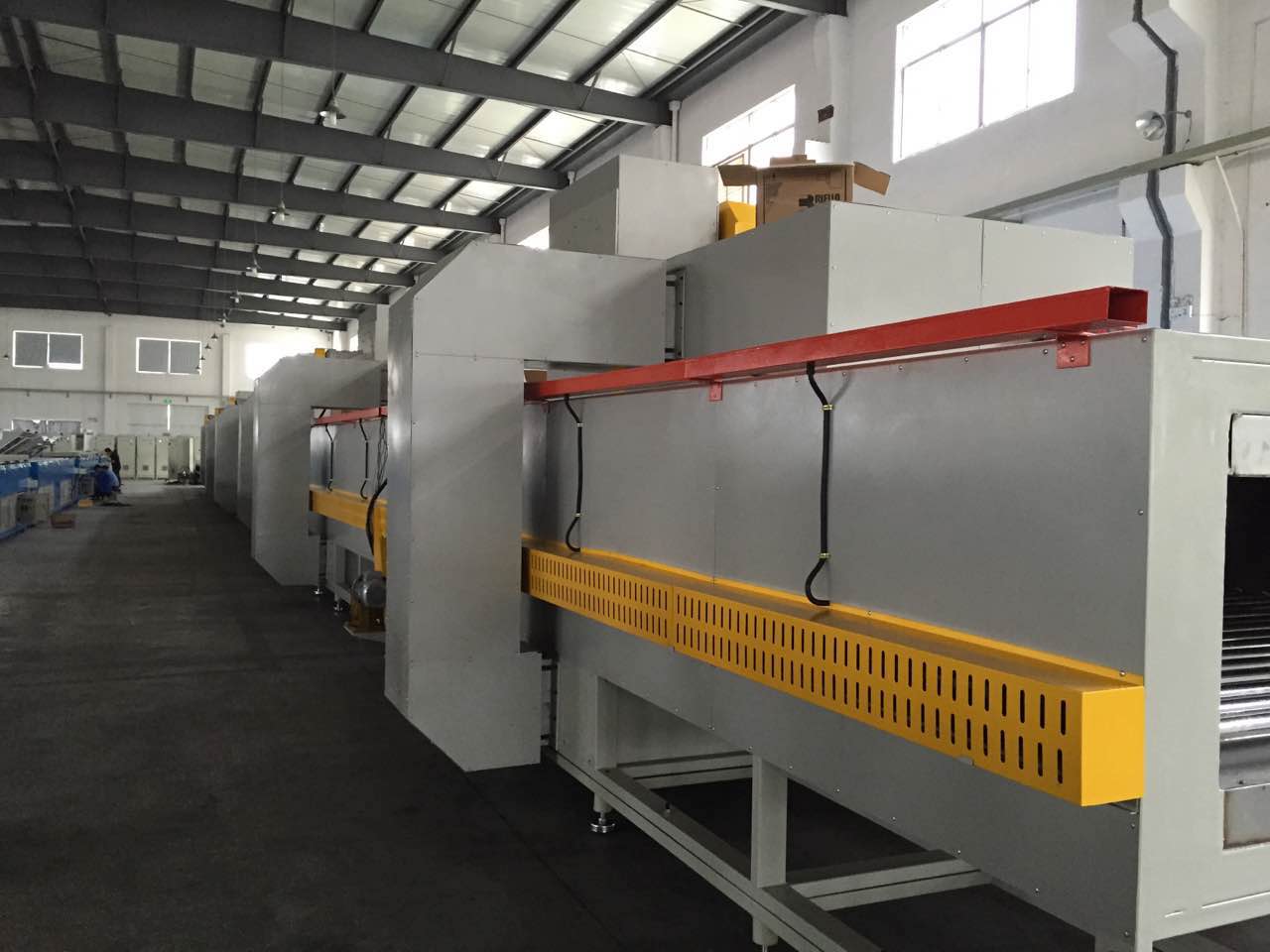
Barrel temperature zones shape the melt before it ever reaches the die, and that thermal history is what ultimately shows up on the profile surface. If the rear zone runs too cold, unmelted polymer granules survive deep into the screw, creating hard particles that tear through the melt film and leave visible streaks or pits. If the front zone runs too hot, the surface layer of the melt becomes overly fluid while the core stays cooler, producing a non-uniform velocity profile that translates into waviness, gloss variation, or rough texture at the profile edge.
The middle zones matter just as much because they control how shear heat builds without pushing the material into degradation. A sudden spike in the compression zone can burn the outer melt layer, causing brown specks or a chalky finish, while a zone that is too cool reduces shear thinning and forces the polymer through the die with higher viscosity, amplifying die lines and surface drag marks. Each zone has a narrow window where the melt arrives at the die with consistent temperature and pressure; stray outside that window and the finish defects are almost immediate.
In practice, chasing a better finish means tuning the barrel profile as a system rather than polishing the die alone. Moving the rear zone up by a few degrees can eliminate micro-tears that look like fine sandpaper, while dropping the front zone slightly can restore a high-gloss surface that had turned hazy from overheating. Because the melt reacts slowly to barrel changes, the operator sees the true finish only after a few minutes of running, so adjustments should be small, patient, and always paired with a check of melt pressure stability.
Custom Die Geometry Without the Usual Trial-and-Error
Shaping a die to produce a precise stamped or formed part has long meant building a first guess, running it, measuring the deviation, and then cutting or welding until the profile finally matches the print. That loop collapses once forming simulation stops being a rough sanity check and starts acting as the primary geometry engine. High-fidelity solvers now account for material anisotropy, blank thickness variation, and tool deflection well enough that springback and sidewall curl are predicted before steel is cut. The die face is then modeled directly against the simulated post-form shape, so the first physical tryout often lands within microns of the target rather than serving as a starting point for iterative grinding.
What makes this approach practical is not just better math but a shift in how geometry is defined. Instead of nesting a nominal part surface inside a generic die body, engineers create compensation fields tied to specific regions—more draw-in allowance where the flange tends to shrink, a slight crown across a wide panel to cancel elastic recovery, a local radius adjustment where strain concentrates. These adjustments live as parametric features, so when the incoming coil properties drift or a new batch of material arrives, the die surface updates through a recipe rather than a new round of hand finishing. The usual trial-and-error becomes a data review, not a shop-floor ritual.
Precision Feeding Systems That Reduce Scrap Rates
Precision feeding isn't just about moving material forward; it's about controlling every micron of advance to match tool engagement. Many stamping and forming operations generate scrap because the feeder overshoots or undershoots the target position by a few tenths of a millimeter. A system built around servo-driven nip rolls and linear encoders can hold feed length repeatability to ±0.02 mm or better, which directly eliminates short shots and overfeed conditions at the die.
Beyond positional accuracy, the timing of material release matters. When the feeder releases the strip too early or too late relative to press stroke, the material can buckle, slip, or stretch. Modern precision systems synchronize feed motion with press angle using high-speed fieldbus communication, compensating for acceleration and deceleration ramps in real time. This prevents micro-slippage that often goes unnoticed but leads to edge cracking and dimensional drift over a production run.
Scrap reduction also comes from better material utilization. With tighter feed length control, you can reduce the coil-end remnant or skeleton web width because you're no longer leaving extra allowance for feeder error. Some shops have cut their scrap rate by 3 to 6 percentage points simply by upgrading from pneumatic or mechanical feeders to closed-loop servo units with automatic calibration drift correction. The payback often comes within months, not years, from saved raw material alone.
Inline Curing Options for Tight Tolerances
Tight dimensional tolerances often fall apart during curing if the energy source is inconsistent. Batch ovens create slow, uneven heating that leads to warpage or internal stress, but inline systems can apply a focused dose of UV light or heat exactly where needed, while the part is constrained in a fixture. This immediate, localized energy transfer limits the time for thermal drift to accumulate.
For high-precision bonding or coating, focused UV LED arrays provide millisecond-level cure times with minimal heat spread, keeping delicate components stable. When a thermal cure is required, pulsed hot-air nozzles with integrated temperature feedback adjust airflow in real time to avoid hot spots, while short-wave infrared emitters can cure a thin resin layer without raising the core temperature of the part. Each method works best when the curing profile is matched to the material's specific response.
Choosing between these options usually starts with the resin's absorption spectrum and the required cure depth. In-line monitoring of part dimensions, using laser micrometers or vision systems, can then verify that the process stays within tolerance throughout a production run.
Preventive Maintenance Checks That Keep Lines Running
Daily shift-start inspections often spot small issues before they snowball. Operators walking the line with a simple checklist—checking belt tension, air pressure at key manifolds, and sensor lens cleanliness—catch misalignments or debris that would otherwise trigger micro-stops later. These five-minute walkarounds replace the old habit of waiting for a fault light.
Weekly and monthly tasks focus on wear items that don't fail suddenly but degrade with cycle count. Greasing linear rails, measuring chain stretch, checking torque on vibration-prone fasteners, and logging hydraulic fluid temperatures build a trend history. When one reading drifts outside its normal band, maintenance can swap a bearing during planned downtime instead of at 2 a.m. after a jam.
The most overlooked checks are often electrical: verifying terminal tightness in high-vibration cabinets, looking for discolored contactors, and using a thermal camera on motor connections. A loose lug or a hot spot caught early prevents intermittent faults that stop a line without leaving a clear error code. Pair these with photo-eye alignment after every product changeover, and the line keeps its rhythm across shifts.
FAQ
Start with the full range of profile cross-sections and rubber compounds you expect to run, then add about 20% extra capacity for future variants. Check that the extruder's L/D ratio suits your main compounds—16:1 works for many EPDM blends, while high-filler or silicone stocks may need 20:1 or more. Also compare the screw cooling options and confirm the downstream modules can be rearranged without major floor changes.
Material choice changes everything from screw compression ratio to die swell compensation. EPDM profiles often tolerate a shallow, single-stage screw, but high-hardness nitrile or FKM stocks can generate excess shear heat, so you need tighter barrel temperature bands and possibly a vented barrel if moisture or volatiles are a concern.
For dense profiles, keeping each barrel zone within ±2°C is more important than chasing an exact setpoint. Use separate cooling loops for feed throat and screw, and place the melt temperature probe close to the die entry—not just in the adapter—so you can catch overheating before it changes the profile's surface finish.
A vacuum spray chamber or vacuum sizing tank matters more than the number of cooling troughs. The vacuum level should be adjustable from about -5 to -30 kPa, because deeper vacuum can correct corner radius but too much can create drag lines. Add a laser micrometer right after the puller so you get live wall thickness data.
Use preheated die heads and pre-blended compound strips instead of feeding cold slab directly. Start the line at low screw speed with the haul-off slightly faster than extrusion speed, then reduce haul-off once the first meter meets target dimensions. Save the first good profile section from each run as a visual reference.
Microwave systems work well for large, thick profiles where uniform core cure matters, but they need polar compounds; EPDM is mostly transparent unless you add carbon black or polar additives. Salt bath gives fast heat transfer and supports continuous cure of complex shapes, but it requires post-wash and salt recovery. Hot air is lowest cost but often too slow for profiles thicker than 8–10 mm.
Because vacuum calibration pulls the soft extrudate against a precision sizing die, it holds corners and internal webs much better than simple water quenching. Open-tank cooling lets the profile float and shrink unevenly, which is why you see twisted or oval parts. The vacuum chamber should be placed within the first 500 mm after the die face for best effect.
Plan modular stations with fixed utility drops and a straight centerline, leaving at least 6 meters of free space before the first cooling unit. That way you can insert a second extruder for co-extrusion or swap in a larger haul-off without moving walls. Also keep the control cabinet on the same side as the main operator path.
Conclusion
For OEM rubber profile extrusion lines, holding shape and surface quality starts well before the die. The screw geometry has to match the compound's viscosity and filler loading—running a high-shear design through a scorch-prone EPDM batch will only create burned specks and downtime. Once that pairing is right, barrel temperature control becomes the next lever because uneven zones along the barrel pull the material differently, leaving waves, porosity, or dull edges that no downstream polishing can fix. Skilled tooling engineers now simulate flow through custom die channels, so land lengths and relief angles are adjusted on screen, not by grinding three test dies. That removes most of the trial-and-error from new profile launches.
Feeding consistency is where scrap quietly accumulates. A slight surge in strip feed rate changes the die pressure enough to widen corners or create sink marks, so precision feeders with closed-loop weight or volume control keep output uniform without constant operator correction. For profiles that must hold tight dimensional tolerances, inline curing methods such as salt bath, microwave, hot air, or a hybrid let you dial in the exact heat history instead of relying on a separate batch cure. And because all of this hardware only works if it stays in adjustment, a short daily checklist for screw wear, thermocouple drift, feed roll tension, and die land cleanliness prevents the kind of slow drift that turns into a full line stoppage. Rather than chasing individual fixes, manufacturers get the most from treating screw, barrel, die, feed, cure, and maintenance as one continuous system.
Contact Us
Contact Person: Chen Zhengwei
Email: [email protected]
Tel/WhatsApp: +86-13963975727
Website: https://www.sfcrubbermachine.com